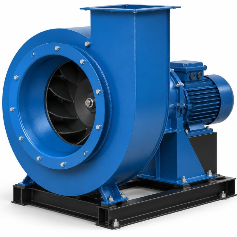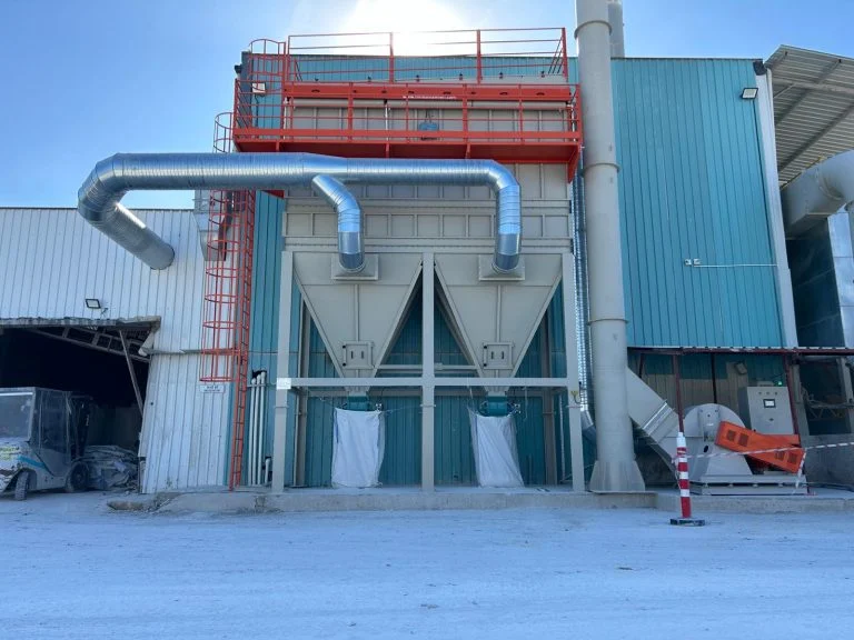







Fan airflow refers to the volume of air a fan moves per unit of time and is given in cubic meters per hour. The calculation is based on two values: the duct cross-section and the air velocity through that cross-section.
When the airflow calculation is wrong, the result causes problems in both directions. An undersized fan leaves the suction weak, while an oversized fan wastes energy and puts unnecessary strain on the line.
What Is Fan Airflow?
Fan airflow is the amount of air the fan moves at its operating point. It is not the maximum value stated in the catalog, but the actual value the fan delivers against the resistance of the line it is connected to.
This distinction is critical. If a fan is listed in the catalog at 25,000 cubic meters per hour, that value applies at zero pressure; once it is connected to ducts and a filter, the resistance increases and the airflow drops. The actual airflow of the fan is read at the point where the fan curve intersects the system resistance curve. The same fan can deliver two different airflows in two different plants, because the decisive factor is not the fan itself but the resistance of the line it is connected to.
How Is Fan Airflow Calculated?
The fan airflow calculation starts from the plant’s requirement, not from the fan. First, the amount of air the line needs to draw is determined, and then a suitable fan is selected based on that value.
- Identify the extraction points: list the hood size and number for each machine
- Select the capture velocity: determine the required air velocity based on the dust character
- Calculate the point airflows: multiply the hood cross-section by the velocity for each point
- Apply simultaneity: account for the proportion of points operating at the same time
- Determine the total airflow: add up the point values
- Add the pressure drop: calculate duct, elbow and filter resistance
- Select the fan: choose the model that meets both airflow and pressure
When this sequence is reversed, errors become inevitable. Companies that already have a fan usually try to calculate the airflow based on the fan, in other words starting from the value the existing fan can deliver. Calculating airflow from the fan only makes sense as a capacity check; for a new installation, the correct method is to start from the line.
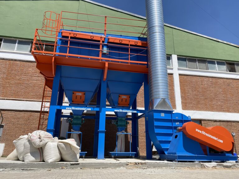
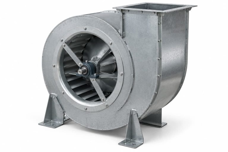
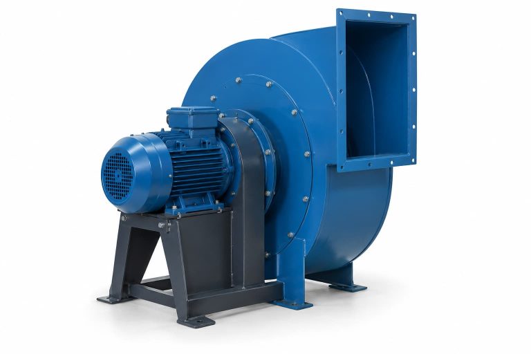
Fan Airflow Calculation Formula
The volumetric flow formula is based on multiplying the cross-sectional area by the air velocity. When an hourly value is required, the result is multiplied by 3,600.
| Quantity | Symbol | Unit | Example value |
|---|---|---|---|
| Volumetric flow rate | Q | m³/h | 21.600 |
| Cross-sectional area | A | m² | 0,4 |
| Air velocity | v | m/s | 15 |
| Air density | ρ | kg/m³ | 1,2 |
| Static pressure | Δp | Pa | 2.500 |
The airflow formula is written as Q = A × v × 3,600. If the air velocity in a duct with a cross-section of 0.4 m² is measured at 15 m/s, the calculation is 0.4 × 15 × 3,600 and the airflow comes out at 21,600 m³/h. In a circular duct the cross-sectional area is found from the diameter; the area of a duct with a diameter of 400 millimeters is calculated as 0.1256 m². When applying the airflow formula, the velocity must be measured as the cross-sectional average rather than at the center of the duct, otherwise the result will be too high.
The Relationship Between Fan Pressure and Airflow
When calculating pressure and airflow, it should not be forgotten that the two move in opposite directions. As the resistance of the line increases, the airflow passed by the same fan decreases.
System resistance grows with the square of the airflow, which means that doubling the airflow quadruples the pressure drop. In terms of fan speed, the relationship is defined by the fan laws. When the speed is increased from 1,500 to 1,800, the ratio is 1.2: airflow increases 1.2 times, pressure rises 1.44 times and power demand rises 1.728 times. For this reason, pressure and airflow calculations for speed changes must always be accompanied by a power check.



Airflow Calculation by Fan Type
The formula is the same for every fan type; what changes is which pressure value is used as the basis. The fan type is selected according to the resistance of the line.
Some of the distinctions here stem from naming. A radial fan is technically the straight-bladed subtype of the centrifugal group, but on the market the two are searched for as if they were separate products. There is no difference in terms of calculation; the difference lies in which efficiency value and which pressure drop are used.
Radial Fan Airflow Calculation
Radial fan airflow is calculated based on dirty filter resistance. Because the straight-bladed impeller handles dusty air, the line becomes more resistant over time, and if the calculation is made with the clean filter value, the fan will be insufficient after six months.
On dust-carrying lines, dirty filter pressure, a dust build-up allowance and elbow losses are added to the calculation. When selecting a Radial Fan, power is found by dividing the product of airflow and pressure by the fan efficiency. Once the radial fan airflow calculation is complete, the operating point is marked on the fan curve.
Axial Fan Airflow Calculation
Axial fan airflow calculation is based on the logic of high airflow and low pressure. Because the air moves parallel to the blade axis, this group moves large volumes with little energy.
If the ductwork is short and there is no filter resistance, axial fan airflow can be calculated directly from volume. In filter-connected systems, however, this type is insufficient on its own, because its airflow drops rapidly as resistance increases. Smoke extraction and general ventilation are the main domain of this group; on dust extraction lines, the centrifugal group is used.
Centrifugal Fan Airflow Calculation
Centrifugal fan airflow is calculated with different efficiency values depending on blade shape. Backward-inclined blades offer high efficiency, while forward-curved blades deliver more airflow from the same housing.
The efficiency value used in the calculation directly affects the result. When calculating centrifugal fan airflow with an efficiency of around 0.7, the power required for an airflow of 6 m³/s and a pressure of 2,500 Pa comes out at 21.4 kilowatts. In the Centrifugal Scroll Fan group, this value varies according to blade type.
Ventilation Fan Airflow Calculation
Ventilation fan airflow is calculated from volume and the number of air changes. The formula is written as Q = V × n, where V is the room volume and n is the number of air changes per hour.
If 6 air changes per hour are targeted in a workshop with a volume of 2,000 cubic meters, the airflow is found to be 12,000 m³/h. The number of air changes is selected according to the nature of the space, and this value is higher in areas where welding and painting are carried out. Fresh air intake is also planned separately for the value obtained from the ventilation fan airflow calculation.
How Is Fan Mass Flow Calculated?
Fan mass flow is found by multiplying the volumetric flow by the air density. The formula is written as ṁ = Q × ρ and the result is in kilograms per hour.
Because density changes with temperature, this calculation becomes mandatory on hot gas lines. A density of 1.2 kg/m³ at 20 degrees Celsius drops to 0.75 kg/m³ at 200 degrees. The same volumetric flow of 21,600 m³/h carries 25,920 kg/h under normal conditions but only 16,100 kg/h at 200 degrees, meaning a mass loss of 38 percent. If the fan mass flow calculation is skipped, a fan fitted on a hot line fills the housing but does not move the required mass.

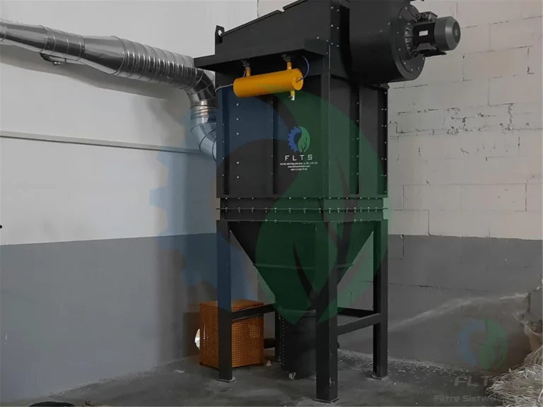
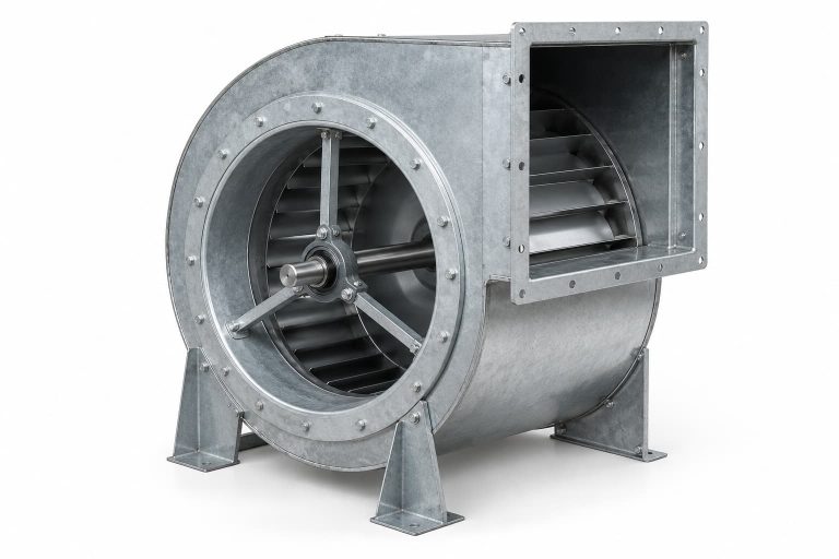
Airflow and Pressure Values in Fan Selection
At the quotation stage, two values are given together: airflow and static pressure. If only the airflow is stated, the right fan cannot be selected, because dozens of fans delivering the same airflow produce very different pressures.
Since catalog values are given for standard air conditions, corrections are applied for hot or high-altitude plants. It is important that the operating point stays close to the efficiency peak on the fan curve; a fan operating at the extremes both creates noise and increases energy consumption. When you fill in our quote form with your line’s airflow and pressure data, we determine the suitable fan type together.
Points to Consider When Calculating Fan Airflow
The factors that distort the calculation mostly come from neglected items. The headings below are the points most frequently overlooked in the field.
- Dirty filter resistance: calculating with the clean filter value leaves the fan undersized
- Simultaneity ratio: if not all points operate at the same time, the airflow is overstated
- Temperature correction: in hot gas, density drops, so pressure also decreases
- Altitude effect: as elevation increases, air density and fan pressure drop
- Leakage allowance: an allowance is left for duct and flange sealing
- Elbows and contractions: local losses are added to the total pressure
- Measurement method: velocity should be taken as the cross-sectional average
- Future capacity: if machines will be added to the line, this is accounted for from the start
When these items are included in the calculation, the result gets closer to reality. When the airflow calculation is completed at the desk and not verified in the field, a discrepancy always emerges, so measurements must be taken with an anemometer during commissioning and the value recorded. The first measurement also becomes the reference value, providing a record for comparison when the airflow drops in later years.