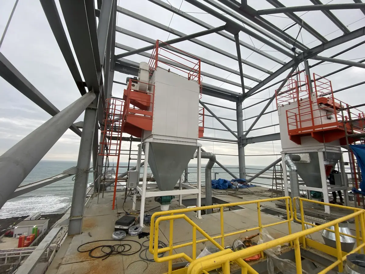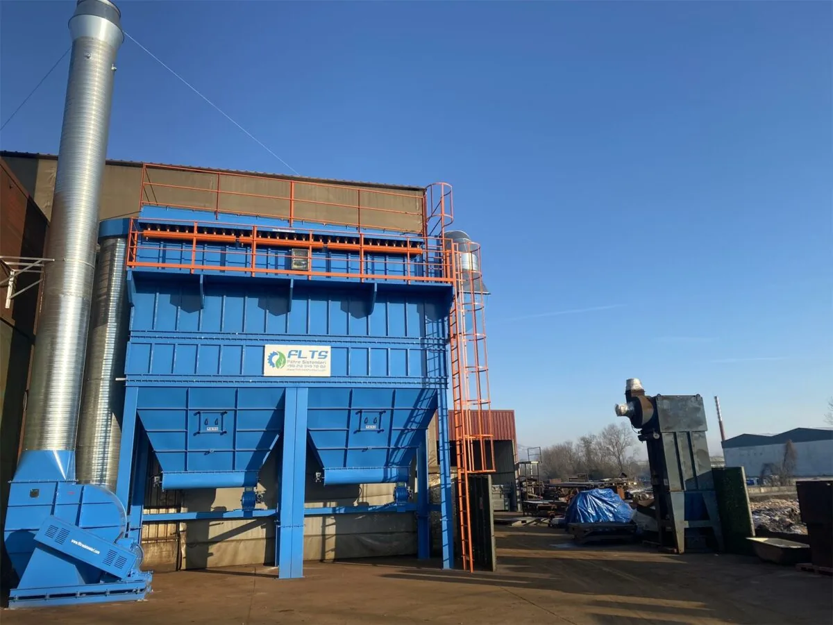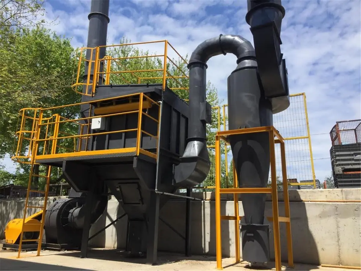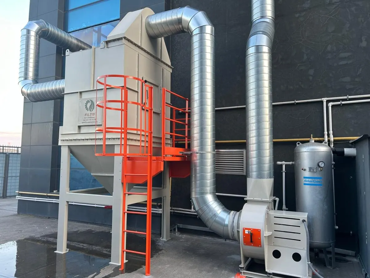









What Are Industrial Filter Systems?
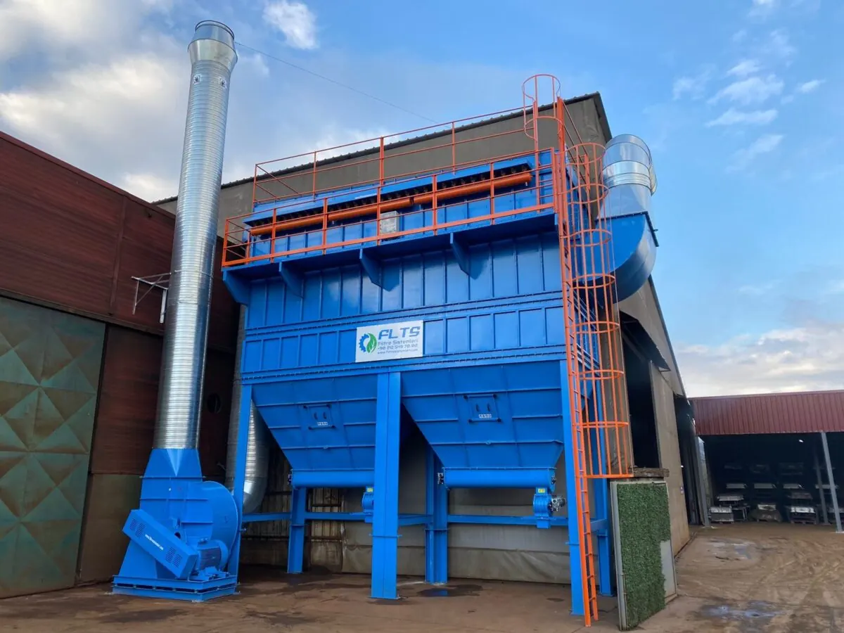
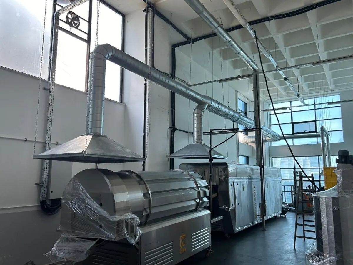
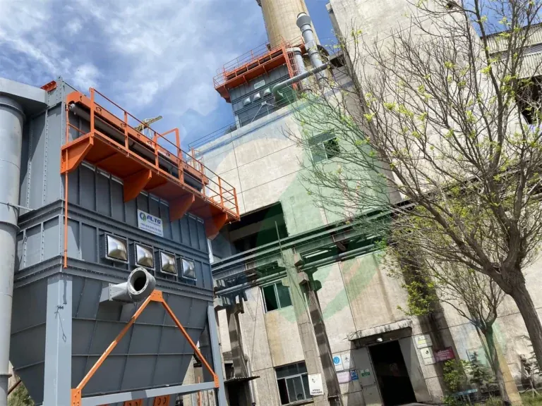
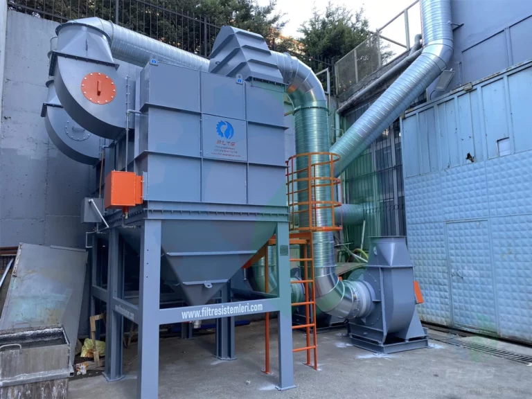
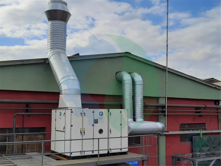
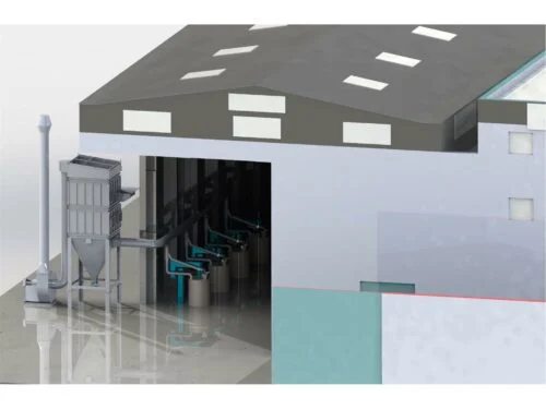
Industrial filter systems are the equipment that captures dust, fumes, oil mist and particulates released into the air during production at the source, holds them on a filter surface and returns the cleaned air to the plant or the atmosphere. A system consists of extraction hoods, a duct network, a filter housing, a fan and dust discharge elements.
FLTS Filtre Sistemleri San. ve Tic. Ltd. manufactures dust collection units, industrial fans and filter spare parts in its workshop in İkitelli OSB, Istanbul. Design, manufacturing, installation, commissioning and system automation are carried out by the same team. Every project is sized from measurements taken at the plant, not built on an off-the-shelf catalogue product.
What does an industrial filter system do?
The task of the system comes down to three things: reducing respirable particulates in the working area, keeping stack emissions below legal limits and returning valuable dust to the process. On flour, feed, cement and plastics lines, the material collected under the hopper can be fed back into production. Because dust that would settle on machine slides, bearings and electrical panels is captured at the source, equipment life is protected as well.
Components of an industrial filter system
A system is not a single housing but a set of connected parts. Choosing one part wrongly reduces the performance of the others.
- Extraction hoods and inlets on the machine or workstation
- The duct network, elbows and dampers that carry dust to the filter
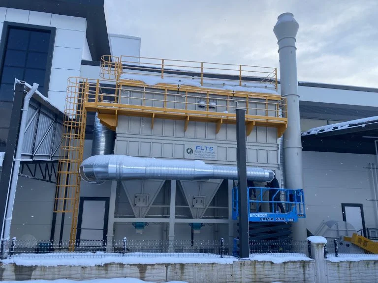
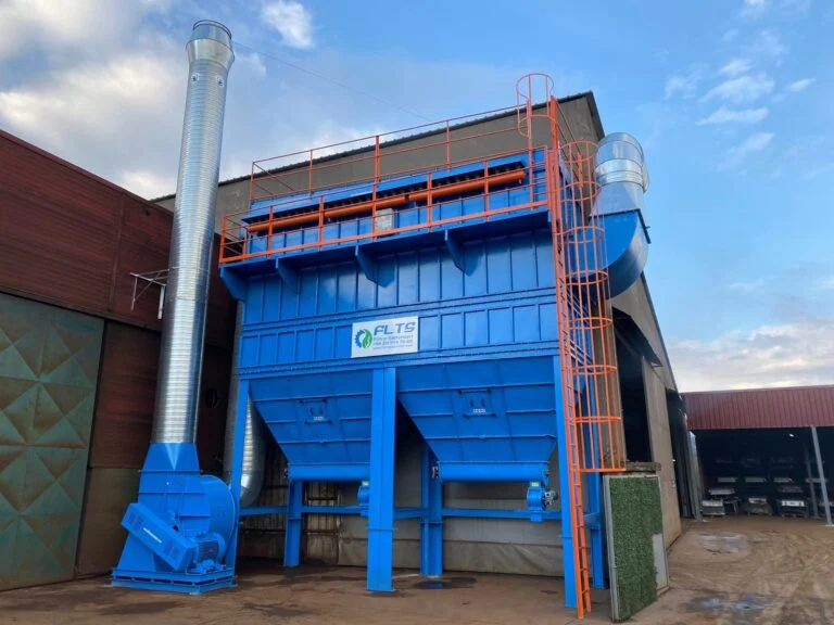
- The steel housing that holds the filter bags or cartridges, the clean air plenum and the hopper
- The compressed air tank, pulse valves and control panel
- The fan that creates negative pressure in the line and the discharge stack
- The airlock, screw conveyor or conveyor under the hopper
Dust collection versus general ventilation
General ventilation dilutes the whole volume of a hall with clean air. Dust collection systems, on the other hand, capture particulates where they are released and stop them from spreading through the rest of the plant. That is why one system cannot replace the other; in plants that generate heavy dust, local extraction and general ventilation are engineered together.
How Do Industrial Air Filtration Systems Work?
Industrial air filtration systems work through extraction, conveying, filtration and cleaning: the fan creates negative pressure in the duct network, dusty air is drawn into the filter housing, particulates stay on the filter surface and clean air is discharged. As the filter surface loads up, the cleaning system starts and production continues without stopping.
Extraction and conveying
Each machine’s extraction inlet needs enough capture velocity to draw the dust into the duct. The inlet should face the direction the dust is released and sit as close to the source as possible. If the conveying velocity in the duct drops, dust settles on the duct floor, so wide-radius elbows are used instead of sharp bends.
Filtration
When dirty air enters the filter housing its velocity drops and coarse particles fall straight into the hopper. Fine dust sticks to the bag or cartridge surface, while clean air passes through the filter media into the clean air plenum. The dust cake that forms on the surface slightly increases collection efficiency, but as the layer thickens the pressure drop rises and extraction weakens.
Jet pulse cleaning
A diaphragm pulse valve sends compressed air from the air tank through a blow pipe into the bag or cartridge as a short pulse. The filter element flexes suddenly, the dust cake breaks and falls into the hopper. Because the pulses move row by row, only one row is cleaned at a time while the remaining elements keep filtering.
Cleaning is triggered in two ways. In timed operation, pulses are released at fixed intervals. In differential pressure control, cleaning starts when the difference between the dirty and clean sides exceeds a set value. The second method is preferred because it reduces compressed air consumption and filter wear.
Dust discharge
Dust collected in the hopper is transferred by an airlock, screw conveyor or conveyor into a big bag, a bin or back into the process. Discharge under the hopper has to work reliably, because a full hopper makes dust climb back onto the filter elements.
Types of Dust Collection Systems
Dust collection systems differ by particle size, moisture, temperature and combustibility of the dust; no single type suits every plant. The main systems FLTS manufactures are summarised below together with the conditions in which they are chosen.
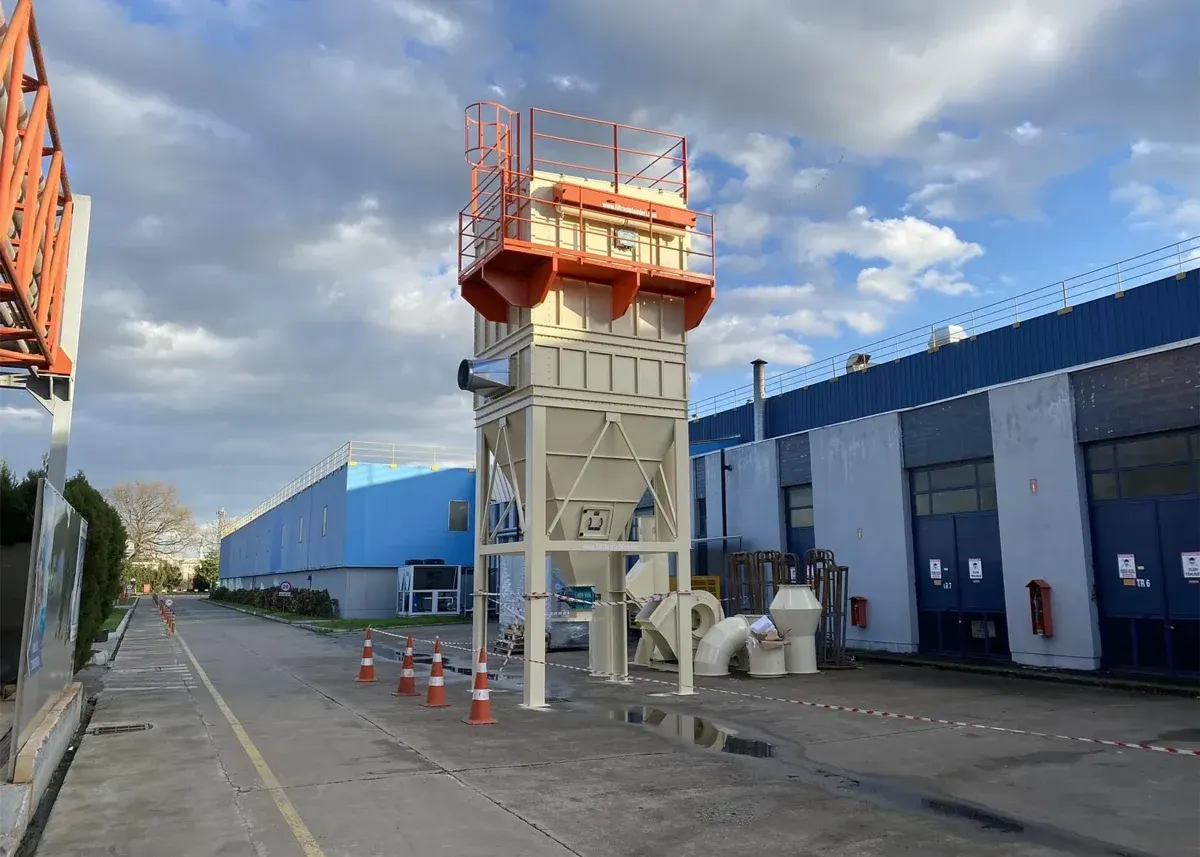
Jet Pulse Bag Filter
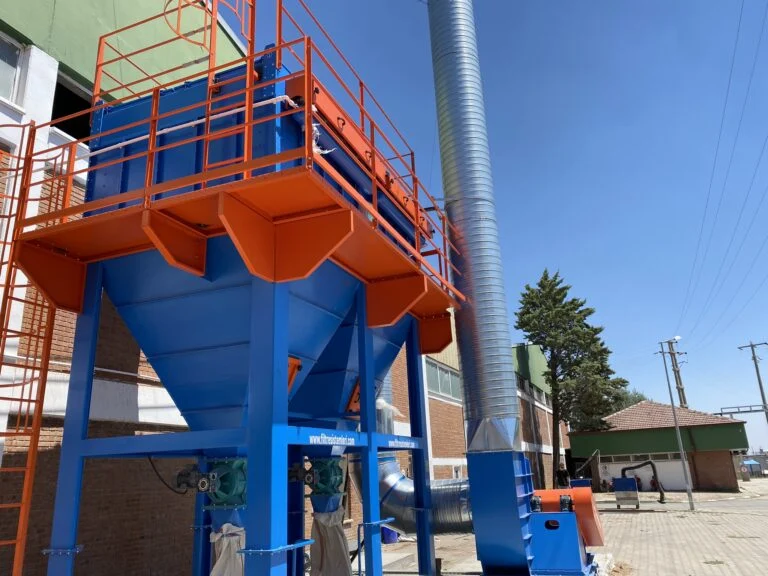
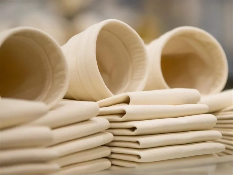
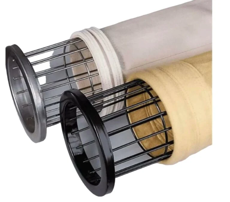
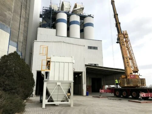
A jet pulse bag filter is a dry system that holds dust on the outer surface of filter bags fitted over cages and cleans the bags automatically with compressed air pulses. It is used on lines with high dust loads that run continuously, and is common in foundries, cement, wood, grain and recycling plants. The bag fabric is chosen by gas temperature, moisture and acidity, and the fineness and combustibility of the dust; polyester, antistatic, meta-aramid or PTFE membrane bags can be fitted to the same housing.
Jet Pulse Cartridge Filter
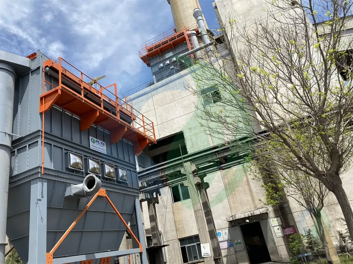
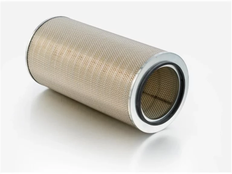
A jet pulse cartridge filter holds dry dust and fumes on pleated cartridge elements. Because the pleats provide a larger filter area in the same volume, it gives high collection efficiency for fine, dry dust. It is preferred for welding fumes, laser and plasma cutting, and in plants with limited space. If the dust load is high or the gas is hot, a bag design is more suitable.
Cyclone Filter
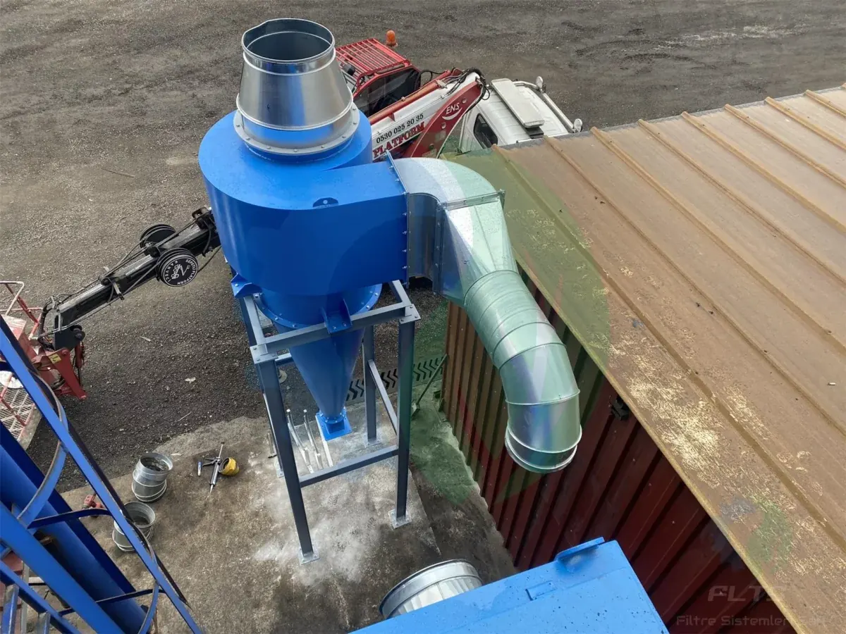
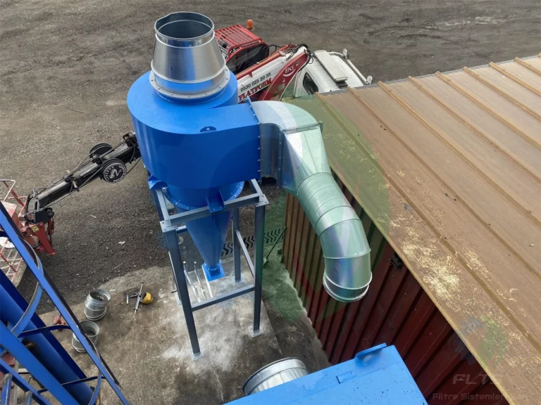
A cyclone filter separates coarse particulates from dusty air through a swirling motion inside the body, without using any filter surface. In most projects it is placed in front of the main filter as a pre-separator. On woodworking lines, coarse chips are held in the cyclone, only fine dust reaches the bag filter and bag life is extended. With abrasive dust it also protects the inlet area of the main filter.
Wet Filter
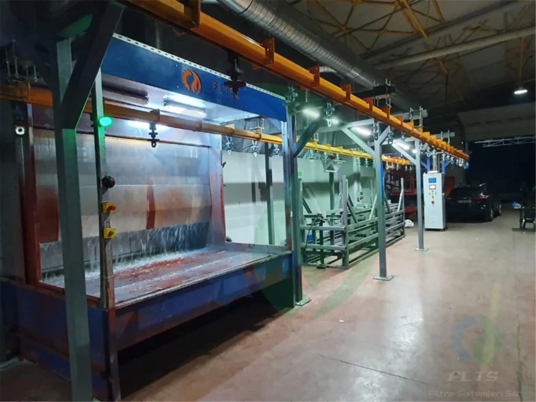
A wet filter is a wet-type unit that passes dirty air through water turbulence so the dust settles in the water. It replaces a dry filter for sparking, sticky or combustible dust and stands out for safety on aluminium sanding and grinding lines. Because the collected dust turns into sludge, it does not become airborne again inside the plant.
Stack Filter
A stack filter captures dust, fumes and particulates leaving industrial stacks before they are released into the atmosphere. It is installed at boiler and combustion plants and on lines where emission measurements exceed the limit. On lines carrying hot flue gas, a gas cooling unit is added in front of the filter to bring the gas temperature down to a level the filter material can withstand.
Oil Mist Filter
An oil mist filter separates oil mist, oil vapour and oily particulates generated by CNC machines, presses and machining equipment from the air. When oily air is sent to a dry dust filter, the filter media clogs quickly, so oil and emulsion vapour need a separate filtration stage.
Sandblasting Filter
A sandblasting filter captures the paint, rust and coating dust removed from surfaces in blasting cabins and blasting machines, together with broken abrasive grains. This dust is abrasive, so the filter media, inlet area and cleaning system are chosen accordingly. On surface preparation lines, filter element replacement is also part of the regular maintenance plan.
Fans and Ventilation
Every dust collection and ventilation system runs on a fan; the fan type is chosen by whether the air being handled is clean, dusty, hot or explosive. The right fan delivers the calculated airflow against the total pressure loss of the system. Weak extraction, dust settling in ducts and unnecessary energy consumption are often caused by a wrongly selected fan.
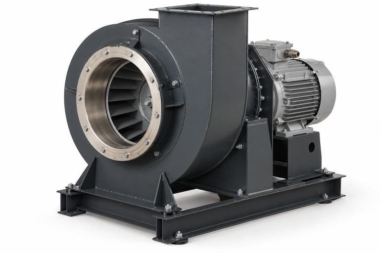
FLTS builds industrial fans to measure from the airflow, pressure, temperature and dust data of the line. The casing can be mild steel, stainless or galvanised sheet; the drive is direct-coupled or belt-driven. Impellers are dynamically balanced after manufacturing.
Centrifugal fans
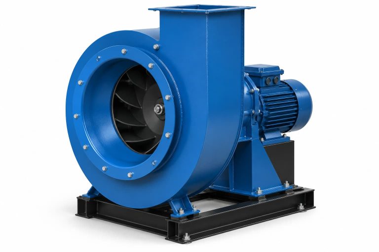
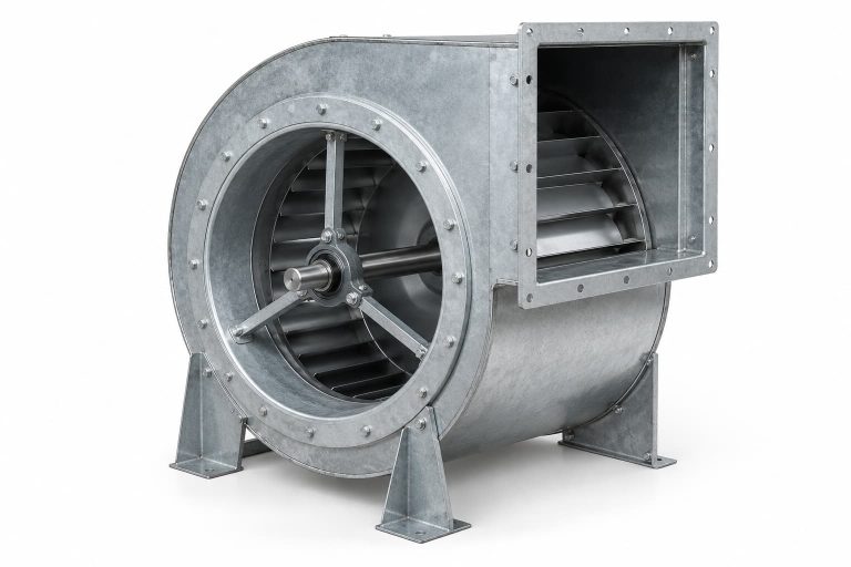
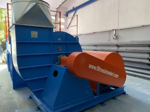
A centrifugal fan throws the air entering the centre of the impeller out to the blade tips and discharges it through a spiral casing. Because it generates high pressure, it is preferred for long duct runs and filtered dust collection systems. Because of its spiral casing it is also known on site as a scroll fan. On filtered lines the fan is usually placed after the filter unit, so the impeller receives cleaned air and wear and imbalance are reduced.
Radial fans
A radial fan, with its straight-bladed impeller, conveys abrasive and sticky dust without letting it build up on the blades. Where dust has to pass through the fan, a radial type with a heavy plate casing is used. On high-airflow lines in cement, iron and steel and energy plants, wear plates are added to the blade surfaces to extend impeller life.
ATEX-rated fans
Where combustible dust or gas is present, an ATEX explosion-proof fan built not to produce sparks is used. In wood, powder coating, flour, sugar, chemical plants and paint shops with solvent vapour, the fan casing, impeller and motor are selected together according to the zone classification.
Factory ventilation
Where local extraction cannot reach, the general air of the hall is replaced with factory ventilation systems. These lines need high airflow at low pressure, so axial fans and industrial extractors are the usual choice. Heat removal and fresh air supply are planned in the same project.
Filter Spare Parts
Filter spare parts are the parts that are replaced regularly or renewed after a failure to keep a dust collection unit running: bags and cartridges are consumables, while cages, pulse valves, explosion vents and airlocks make up the mechanical and safety side of the unit. Parts are made to measure in the İkitelli OSB workshop. When parts are needed for another brand’s unit, the dimensions of the old part are usually enough.
Filter bags
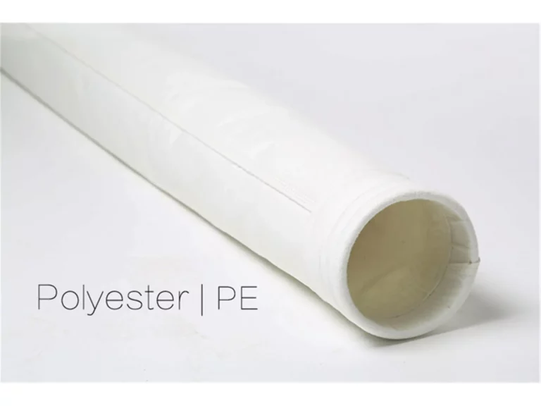
Filter bags are made from polyester, antistatic, meta-aramid (Nomex), PPS, polyimide (P84), PTFE, acrylic, polypropylene and fibreglass fabrics. Polyester is used for general-purpose dry dust, Nomex on hot lines such as foundry and asphalt, PPS and P84 for acidic flue gas, and PTFE in harsh chemical environments where other fabrics wear out quickly.
Filter cartridges
Filter cartridges hold dry, fine dust with their pleated surface. Flanged, conical, panel and antistatic cartridge options are chosen by how the unit is connected and how combustible the dust is. There are separate cartridge types for laser and plasma cutting.
Filter cages
A filter cage supports the bag from the inside and keeps its shape during the pulse. Cages are checked whenever bags are replaced; a bent or rusty cage tears a new bag within a short time.
Pulse valve and control panel
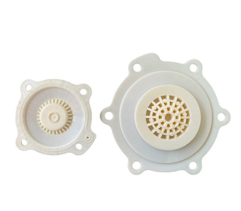
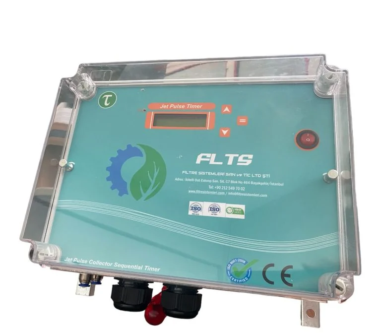
The pulse valve diaphragm is the part that delivers the cleaning pulse, and it wears depending on compressed air quality. The pulse valve control panel manages the pulse sequence, duration and pause interval. Fitting a moisture trap on the compressed air line protects diaphragm life.
Explosion vent
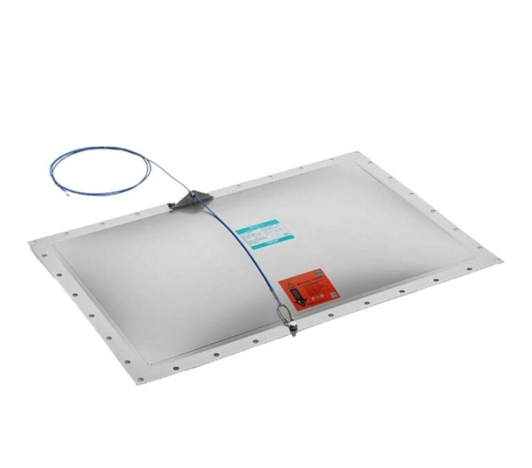
On units handling combustible dust, an explosion vent is added to the housing and the relief direction is turned to a safe side. An antistatic bag or cartridge alone is not enough; earthing, explosion relief and, where needed, a flameless vent are planned together.
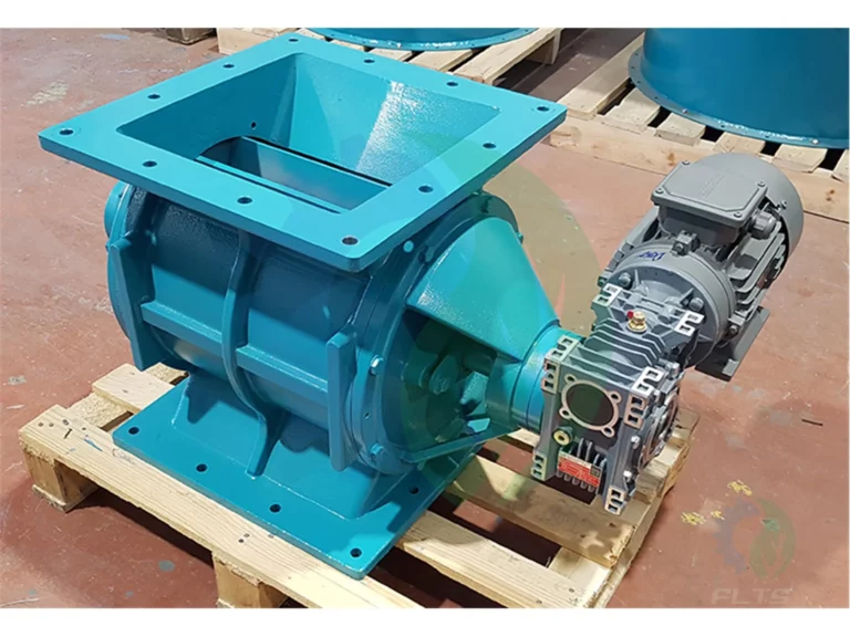
Airlock (rotary valve)
An airlock removes dust from the hopper without upsetting the pressure balance of the system and transfers it to a big bag, bin or conveyor. Together with the screw conveyor and slide gate it forms the dust discharge and conveying group.
Filter Selection by Industry
Selecting an industrial filter starts with the type of dust; two lines with the same airflow need different filter systems if one carries wood chips and the other welding fumes. The table below summarises the systems that stand out in commonly served industries. The final selection is made from measurements taken at the plant.
| Industry | Typical dust or fume | Recommended system |
|---|---|---|
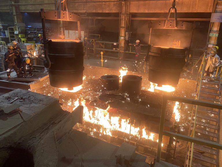
| Foundry, iron and steel | Metal oxide fumes, silica sand dust, sparks, hot gas | Foundry dust collection systems |
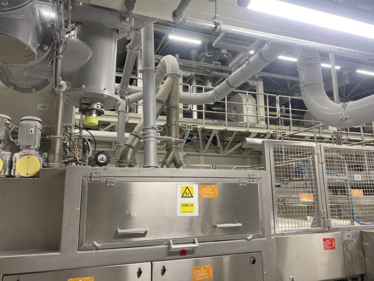
| Food and pharmaceuticals | Flour, sugar, starch, active ingredient dust | Food and pharmaceutical dust collection |
| Cement, lime, aggregates, mining | Abrasive fine dust, high dust load | Jet pulse bag filter |
| Wood and furniture | Chips, sanding dust, combustible dust | Cyclone pre-separator and bag filter |
| Welding, laser and metalworking | Welding fumes, cutting fumes, grinding dust | Jet pulse cartridge filter |
| Painting and coating | Paint particles, solvent vapour | Water curtain wet paint booth |
| Silo, feed and grain | Pneumatic conveying and filling dust | Silo top jet filter |
| Machining (CNC) | Oil and emulsion vapour | Oil mist filter |
The same logic applies to cases not listed in the table. Stack filters with gas cooling units stand out at boiler and combustion plants, sandblasting filters on blasting lines and wet filters in processes with wet and sticky dust. In chemical and plastics plants, antistatic cartridge filters and ATEX fans are considered together for combustible fine dust.
How to Choose the Right Filter System
The right filter system is chosen by considering dust character, airflow, gas temperature, combustibility and installation space together. A selection made before these points are clear may look adequate on paper but fail to deliver the expected extraction on site.
- Dust character: Particle size, moisture, stickiness and abrasiveness determine the filter type and filter media. With abrasive dust a wear allowance is left at the inlet, and a cyclone is used in front for coarse particles.
- Airflow: For each extraction point the capture velocity is multiplied by the inlet area and the values are added up to find the total air requirement. If the share of machines running at the same time is ignored, the unit ends up larger than needed.
- Filter area: The total airflow is divided by the filtration velocity (air-to-cloth ratio) suited to the dust. For fine and sticky dust this ratio is kept low, so the same airflow needs a larger filter area.
- Gas temperature: If the temperature is above the continuous operating limit of the filter media, a gas cooling unit is fitted at the inlet or a heat-resistant fabric is selected.
- Humidity and dew point: On lines with condensation, dust sticks to the filter; housing insulation and fabric are chosen accordingly.
- Combustibility: For combustible dust, antistatic filter elements, housing earthing, explosion relief and an ATEX fan are planned together. If the spark risk is high, a wet solution is considered instead of a dry filter.
- Installation space: Indoor or outdoor location, headroom for filter replacement and the compressed air infrastructure affect the choice between cartridge and bag units.
- What happens to the dust: If collected dust is to be disposed of, a bin or big bag may be enough; if it goes back into the process, an airlock and conveying line are added to the design.
Engineering, Manufacturing and Installation
At FLTS an industrial filter project starts with a site survey, continues with measurement-based design and manufacturing in the İkitelli OSB workshop, and is completed with installation and commissioning on site. Engineering, procurement, manufacturing, installation, commissioning and supervision are managed by one team.
- Survey and measurement: The location of the dust source, the number of machines, inlet dimensions, gas temperature, daily dust quantity and existing duct layout are recorded on site.
- Calculation and design: Extraction airflow, filter area, duct diameters and total pressure loss are calculated. The fan and motor power are selected for the total resistance; the fan calculation uses the dirty filter resistance, not the clean one.
- Manufacturing drawings: Housing dimensions, number of filter elements, valve arrangement, hopper and discharge group are defined and manufacturing drawings are prepared.
- Manufacturing and inspection: The housing is built in the workshop and the welds are checked for tightness. A leaking housing weakens extraction and can release collected dust back into the air.
- Automation: The control panel is prepared for the plant’s automation infrastructure. Remote start and stop, operating status and alarm signals are provided to the plant as dry contacts.
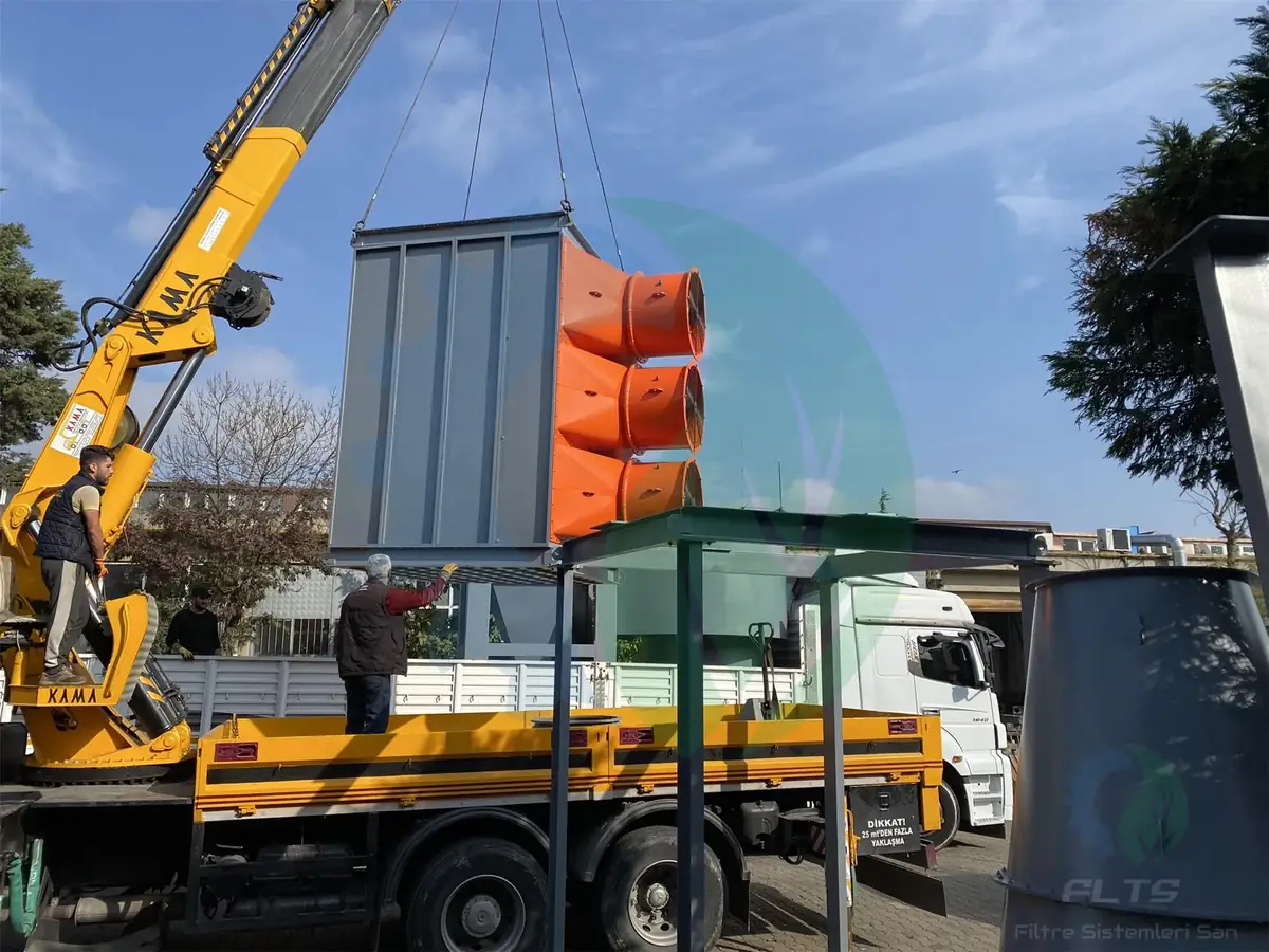
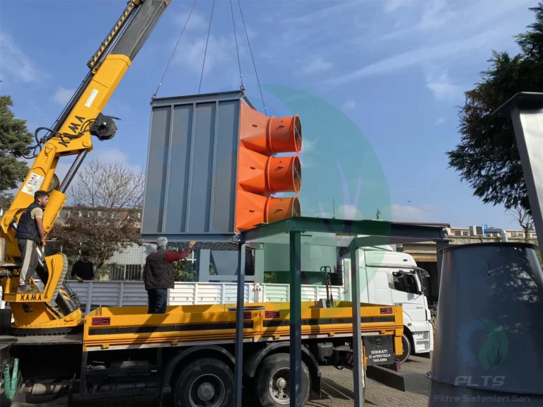
- Shipping and installation: The unit is shipped in sections to shorten installation time on site. The housing, duct connections, compressed air line, airlock and fan are put in place.
- Commissioning: The fan is started, velocities at the extraction points are measured, and the pulse sequence and pause interval are set. The differential pressure between the dirty and clean sides is recorded; this value becomes the reference for later maintenance.
Maintenance and Spare Parts
Maintenance of industrial filter systems centres on monitoring differential pressure; when the value moves outside the reference range, the cleaning system, filter elements and discharge group are checked. Regular maintenance prevents loss of extraction and unplanned downtime.
Filter element replacement
If the differential pressure does not return to its earlier level after a cleaning cycle, or dust is visible at the stack outlet, it is time to replace bags or cartridges. Replacement is done section by section, not one element at a time. When new and old elements run together, air flows towards the new elements and they wear out faster. A differential pressure that stays consistently low may point to a tear or a seating leak.
Periodic checks
- Compressed air pressure, moisture traps and pulse valve diaphragms
- Hopper level and operation of the airlock and screw conveyor
- Straightness and corrosion of the filter cages
- Dust build-up on the fan impeller, bearing noise and temperature, belt tension
- Motor current and vibration level
- Dust settling in the duct network and leaks at flange connections
How to read the differential pressure
The differential pressure recorded at commissioning is the healthy operating value of the unit. If the value rises permanently, the filter surface may be clogging, the cleaning pulse may be insufficient or the compressed air may be wet. If the value drops unexpectedly, look for a tear in a filter element or a leak in the housing. Reading the gauge regularly and logging it lets a fault be spotted before it affects production.
Spare stock planning
On lines that run continuously, keeping spare stock of filter bags, cartridges and diaphragms lets replacements be scheduled around the production plan. FLTS also produces spare parts for other brands’ units from the dimensions or a sample of the old part.
What Determines the Price
The price of industrial filter systems is not taken from a fixed list; it is calculated for each project based on airflow, filter area, materials, fan, automation and installation scope. The evaluation considers operating cost as well as the investment cost.
| Factor | Effect on price |
|---|---|
| Airflow | Determines the filter area, number of elements, housing size and fan power |
| Filter media | Choosing polyester versus Nomex, PPS, P84 or PTFE changes the consumables cost |
| Housing material | Mild steel, galvanised or stainless sheet depends on wear, corrosion and hygiene requirements |
| Fan and drive | Static pressure, motor power, plate thickness, ATEX requirement and the inverter decision |
| Duct network | Duct length, number of elbows, number of inlets and the stack |
| Additional units | Cyclone, gas cooling unit, explosion vent, airlock and conveying elements |
| Automation | Differential pressure control, remote monitoring and the scope of machine integration |
| Installation scope | Site installation, steel structure and commissioning |
A unit with too small a filter area may look attractive at first, but it runs with a higher pressure loss, uses more energy and needs filter elements replaced more often. That is why quotations should be compared on the basis of a technical data sheet.